MAINTENANCE/TROUBLESHOOTING/APPLICATION EXAMPLES
Top of Support & Service > MAINTENANCE/TROUBLESHOOTING/APPLICATION EXAMPLES > How to make maintenance and inspections of station-type soldering irons
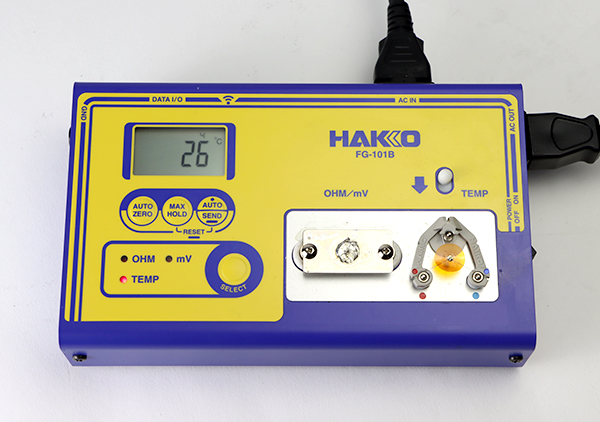
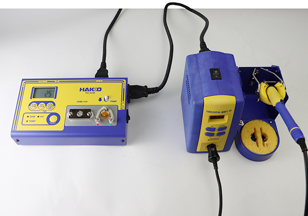
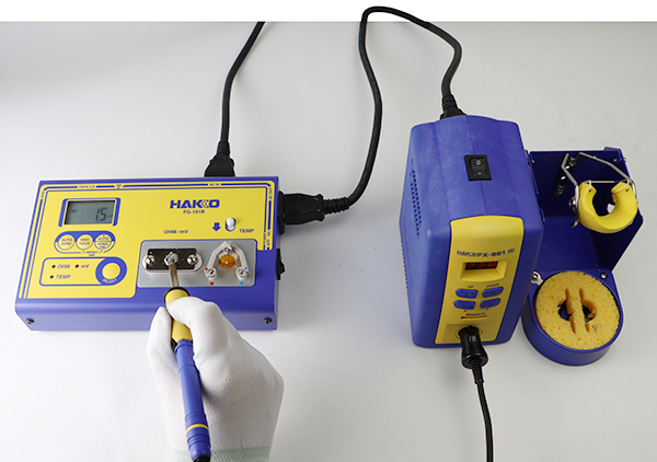
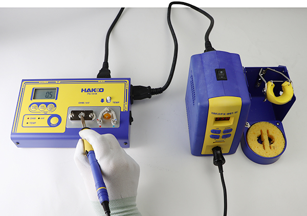
We recommend measuring tip-to-ground potential and tip-to-ground resistance in addition to tip temperature as your daily management for the station-type soldering iron.
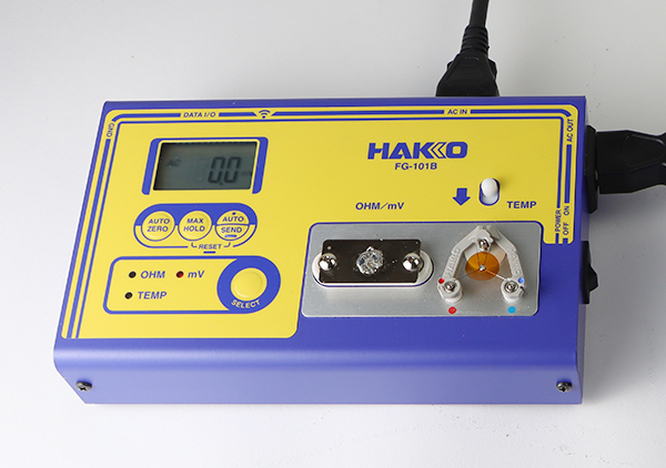
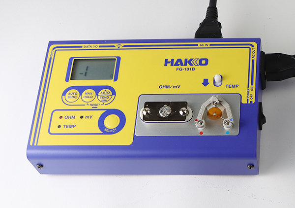
Soldering tester Soldering tester FG-101B
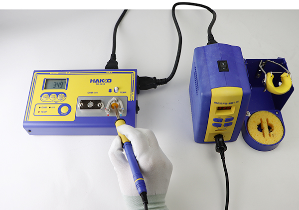
Press the SELECT button to set the mode to ”TEMP”.
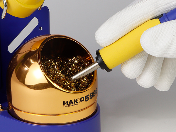
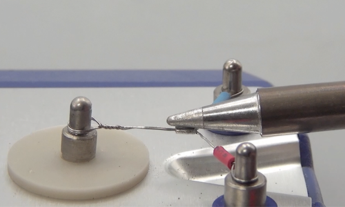
Wipe off the solder on the soldering iron before measuring.
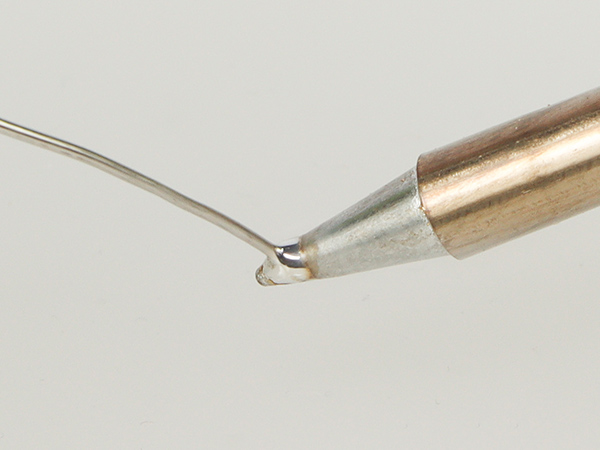
Apply a new coat of solder on the tip.
Touch the tip on the sensor measurement part and feed some solder.
* Contact point or angle may differ according to the tip shape.
Please do not press the tip end to the sensor too much not to break it.
( image of 191-212 discontinued )
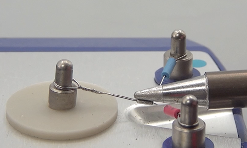
Please do not move the tip until the display shows a stable temperature.
Measure the temperature in a place where there is no airflow from the air conditioner or the like.
Read the value displayed.
Repeat procedures 2 to 5 and record the highest temperature.
Make temperature corrections. ( input an offset value / adjust the CAL )
| Offset indication | -50/-90 | 000 | 050/090 |
|---|---|---|---|
| Offset value input range | -50℃/-90℉ | 0℃ | +50℃/+90℉ |
| Tip temperature | Decreases |
||
Current offset value + Difference in temperature = New offset value
⇒ Input “ -25 ” as the new offset value.
⇒ Input“20” as the new offset value.
Adjust the CAL knob using a tool like a screwdriver.
The following cases may be a cause.
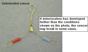
A deteriorated sensor may not be able to measure temperature accurately and shows lower temperature. Replace it with a new one.
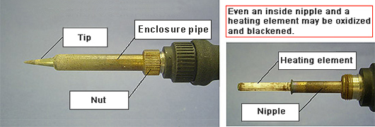
If a tip, tip enclosure, and/or nut are oxidized, soldering iron may have poor heat transfer and show lower temperature. Replace the oxidized parts with new ones.
A length or weight may differ per tip shape. So, changing a tip shape may change thermal capacity, and the tip temperature goes up or goes down. Make temperature adjust-ment (changing offset value / CAL adjustment) with the tip you use.
It is said that the lower the tip-to-ground potential, the better.
The MIL standard specifies that the tip-to-ground potential is designated to be lower than 2mV; therefore, HAKKO performs shipping inspection in accordance with it.
* The MIL standard is a US military-based standard, which has been abolished at present.
Plug the power plug of the soldering iron being measured to the power receptacle of the FG-101B and wait until the tip reaches the set temperature, which is to maximum.
Press the SELECT button and change the mode to ”mV”.
Press the AUTO ZERO button and wait until the display returns normal.
An offset value brought by AUO ZERO is recorded in the unit. So, even if you powered it off, the offset value survives next measurement.
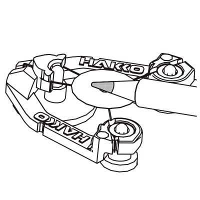
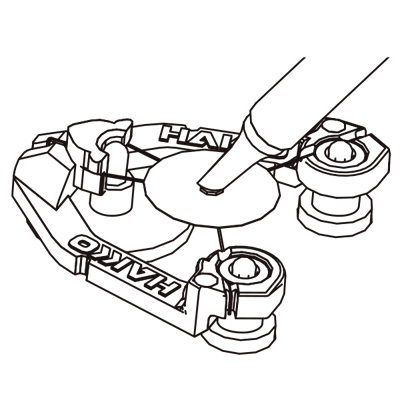
After cleaning the tip, apply a coating of solder to it.
Apply a coating of solder to the center of the conduction plate and heat it until a good soldering wet condition is achieved.
When the display temperature is stable, read the value.
If the heating element has deteriorated (oxidized) due to long-term use, electric current flows to P.W.B. and components from the tip during soldering and generate a harmful effect.
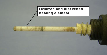
Replace the heating element with a new one.
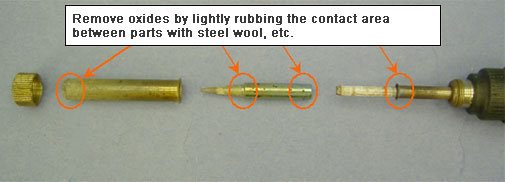
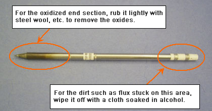
Remove the oxides with steel wool or fine sandpaper.
It is said that the lower the tip-to-ground resistance, the better, as similar to tip-to-ground potential. The MIL standard specifies that the tip-to-ground resistance is designated to be lower than 5Ω; therefore, HAKKO performs shipping inspection with a stricter limit less than 2Ω .
* The MIL standard is a US military-based standard, which has been abolished at present.
Plug the power plug of the soldering iron being measured to the power receptacle of the FG-101B and wait until the tip reaches the set temperature, which is to maximum.
Press the SELECT button and change the mode to ”OHM”.
Press the AUTO ZERO button and wait until the display returns normal.
An offset value brought by AUO ZERO is recorded in the unit. So, even if you powered it off, the offset value survives next measurement.
After cleaning the tip, apply a coating of solder to it.
Apply a coating of solder to the center of the conduction plate and heat it until a good soldering wet condition is achieved.
When the display temperature is stable, read the value.
Oxide and flux stuck on the tip, tip enclosure and nut will cause the tip-to-ground resistance to become higher. As a result of higher tip-to-ground resistance, the tip-to-ground potential will also become higher.
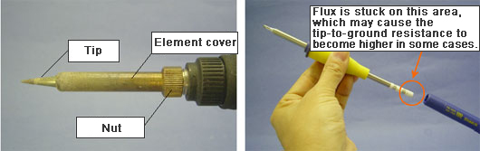
Remove the oxides with steel wool or fine sandpaper.