MAINTENANCE/TROUBLESHOOTING/APPLICATION EXAMPLES
Top of Support & Service > MAINTENANCE/TROUBLESHOOTING/APPLICATION EXAMPLES > S-E (sensor error) is displayed. - Causes and Troubleshooting for the problems in use of of the FM-2027/FM-2028
A station-type soldering iron does not work if S-E (sensor error) appears on the station LCD.
Hereunder is the causes and troubleshooting for the problems in use of the FM-2027/FM-2028.
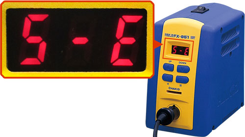
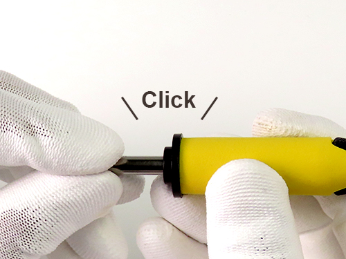
S-E (sensor error) occurs if the tip is not properly inserted all the way to the end.
Please insert the tip in the right procedure.
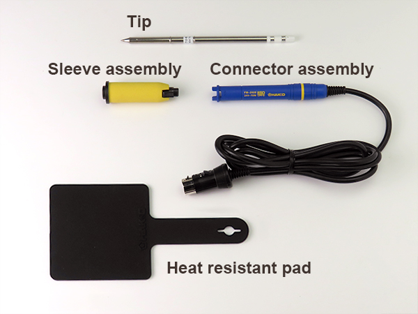
While the tip is hot, please use a heat resistant pad to prevent burns.
The locking parts may be hard to accept the tip when they are still brand new.
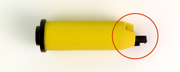
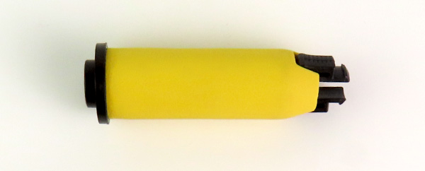
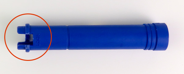
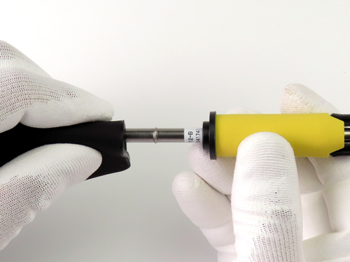
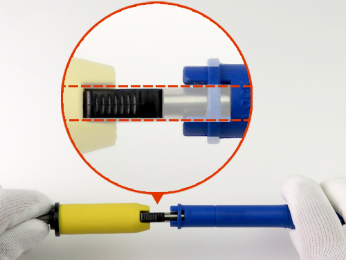
Press down the locking part of the sleeve assembly with the fingers, and insert it into the locking part of the connector assembly halfway.
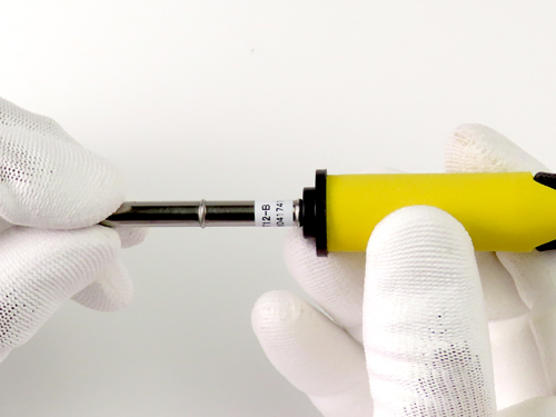
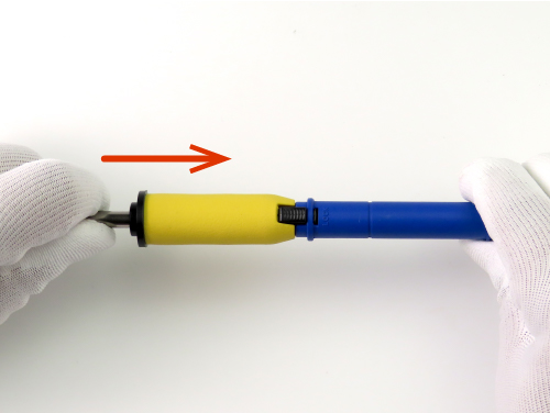
At the end of the process, hold the tip and insert it to the very end.
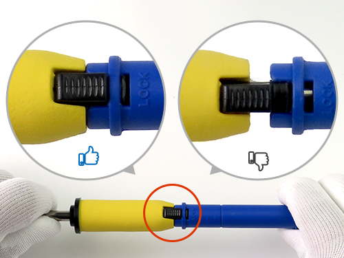
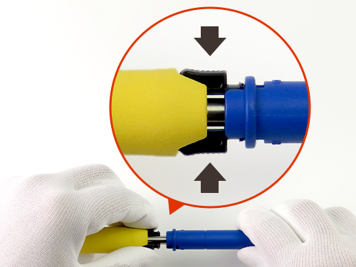
If there is a gap, they are not connected correctly to each other. Please hold the tip and press it all the way to the end.
The heating element inside the tip may disconnent due to degradation over time or drop impact.
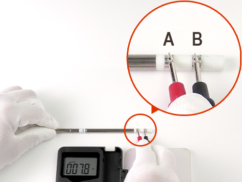
Please check the tip resistance.
If the resistance value is abnormal, the heating element is disconnected. Please replace it with a new one.
If the measured value is normal, please make sure the tip is inserted properly. Tip insertion procedure
Measure the resistance between A and B with a digital multi-meter.
The normal value is8Ω±10%.
Please measure the resistance at room temperature.
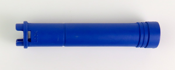
If the sleeve assembly or the connector assembly is broken, the contact between the pats may get loose and cause S-E (sensor error).
Please replace damaged parts.