MAINTENANCE/TROUBLESHOOTING/APPLICATION EXAMPLES
Top of Support & Service > MAINTENANCE/TROUBLESHOOTING/APPLICATION EXAMPLES > How to select the right shape and size of the tip for micro soldering
You can learn how to select the right shape/size of a soldering tip from the examples of soldering electronic components.
Consider the thermal capacity of the P.W.B. and the electric components (size and shape).
It is important to select the soldering tip with enough thermal mass for the boards and components, and a wide contact area to effectively transfer the heat to the soldering point.
Consider the size and shape of the P.W.B. and components for their thermal mass carefully, and select the soldering tip that fits with them well.
Be sure not to select the tip that is too big for the land diameter.
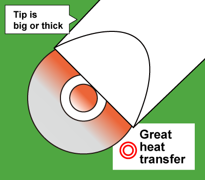
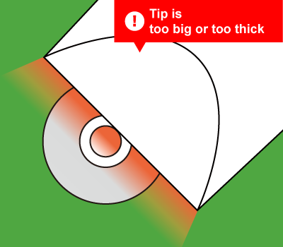
If the tip is bigger than the land, it may damage the land by overheating.
Next, you need to narrow down tip shape and size for suitability to your work.
It is important to understand soldering conditions such as "soldering space is very narrow,"
"there is a tall component next to soldering area", and "a component with a high tendency to occur solder bridging", in selecting the right tip.
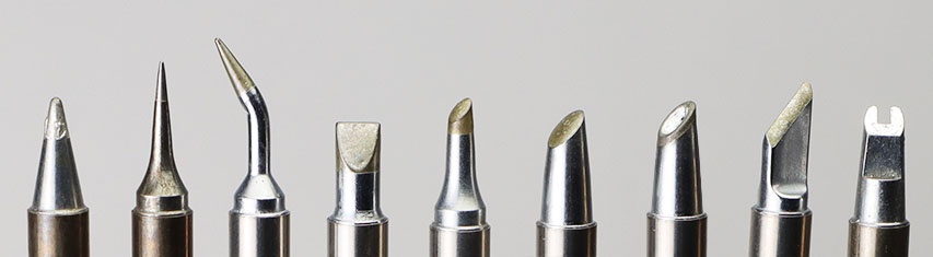
The charasteristics of each tip shape
After narrowing down the tip shape and size considering the thermal capacity of the P.W.B. and the electric components (size and shape), finally, select the one that you think or feel comfortable using.
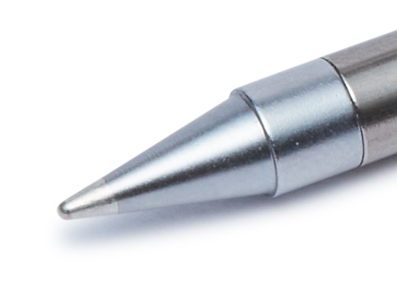
Shape B has a conical tip end like a pencil.
It is useful for various works by using different areas of the tip surface.
Show the example of use Close the examples of use
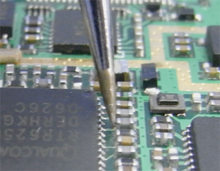
Apply the tip end to the land and slide it slowly in the direction of the red arrows while feeding solder.
Apply the tip end to the leads and drag it slowly in the direction of the red arrows while feeding solder.
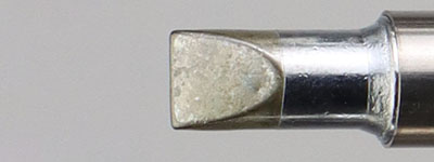
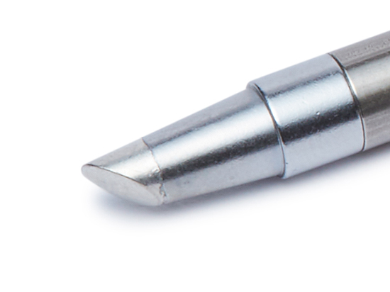
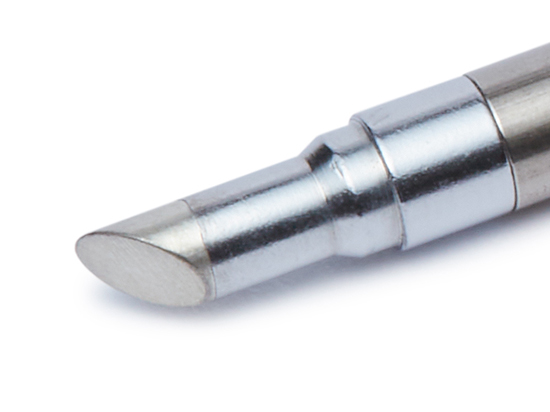
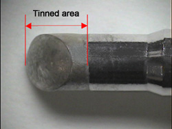
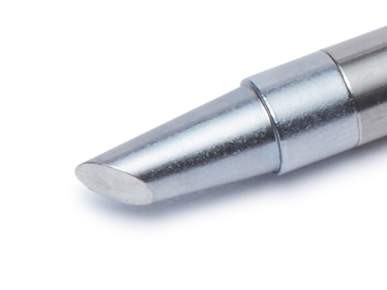
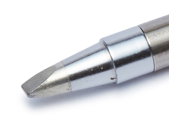
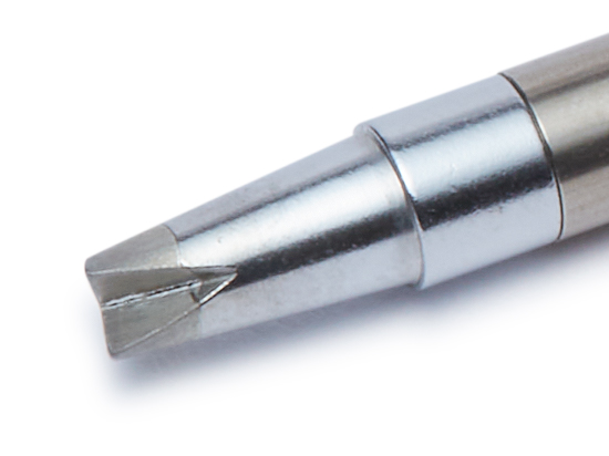
Shape BC/C are like a conical/cylindorical shaft with a diagonal cut.
The main feature is its thickness for great thermal mass, and the cut surface is ideal for soldering.
Show the example of use Close the examples of use
Apply the cut surface to the land and move slowly in the direction of the red arrows while feeding solder.
Apply the cut surface to the lead wire, and slide slowly along the wire while feeding solder.
Apply the cut surface to the coil and terminal to heat them simultaneously and feed solder.
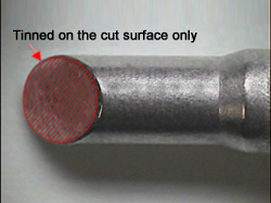
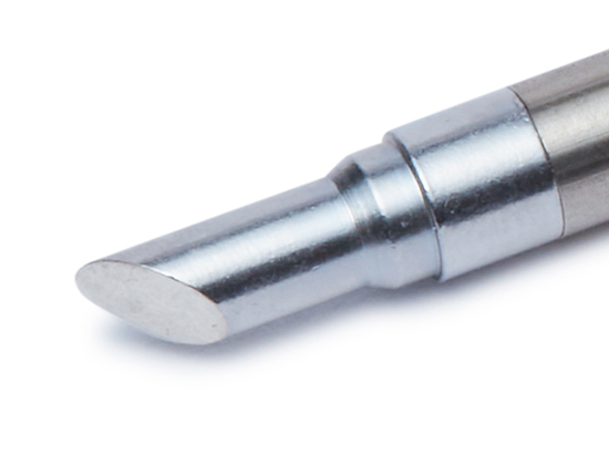
Shape BCF/CF are similar to Shape BC/B but are tinned on the cut surface only.
As the solder does not come up to the tip side, they are more useful than BC/C when soldering with adjacent components.
Difference between BC/C and BCF/CF Close the difference between BC/C and BCF/CF
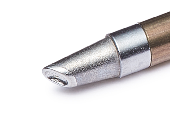
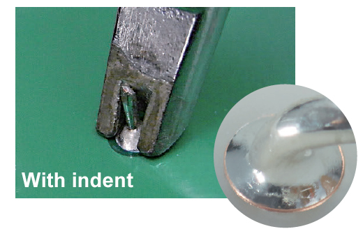
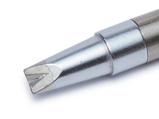
Shape BCM/CM are similar to Shape BC/C in shape but have a dent on the cut surface.
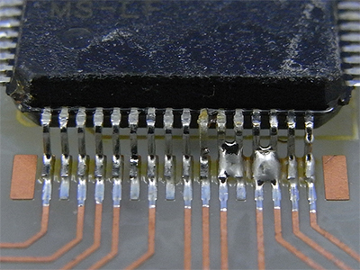
They are suitable for drag soldering because the surface tension of solder in the dent helps prevent solder bridging.
Show the example of use Close the examples of use
Draw the tip slowly in the direction of the red arrows while feeding solder to the dent.
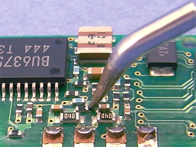
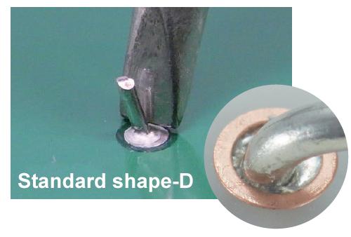
Shape D is similar to a flathead screwdriver.
It has a wider contact area than Shape B, and so it is suitable for soldering chip components and drag soldering.
Show the example of use Close the examples of use
Apply the tip end on the land and drag slowly in the direction of the red arrows while feeding solder.
Apply the tip end to the leads and drag slowly in the direction of the red arrows.
(QFP) Apply the tip end to the leads and drag slowly in the direction of the red arrows.
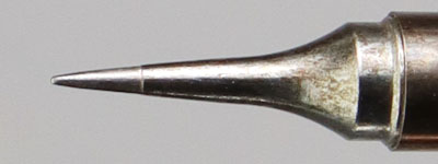
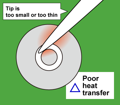
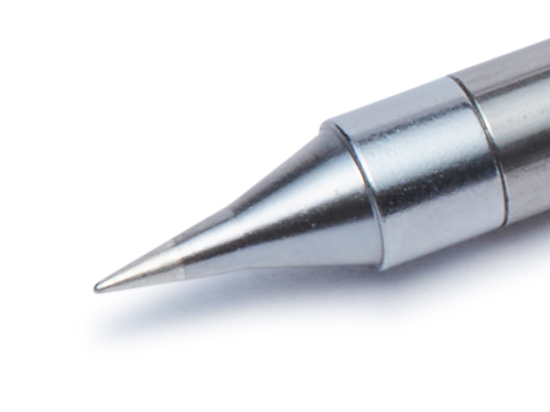
Shape I has a conical tip end like Shape B but quite thinner.
It is suitable for soldering fine components and in narrow spaces.
Show the example of use Close the examples of use
A slim tip end makes it easy to solder fine components.

It is easy to work with shape I for the narrow pitches where the tip end of shape B contacts the components nearby.
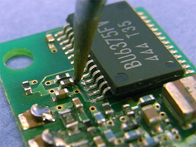
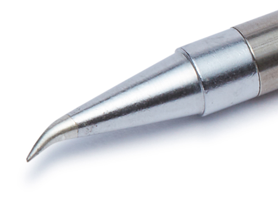
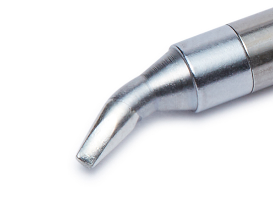
Shape J is the bent type of Shape I or D.
Shape J tips are good for drag soldering with the bent area as well asfor soldering in the narrow spaces.
Show the example of use Close the examples of use
Drag the soldering tip slowly using the bottom surface of tip end.
If there is a little solder, keep the tip upright and slide it in the direction of the red arrows.
If there is too much solder, place the bottom surface of the tip to the bridging area and drag in the direction of the red arrows.
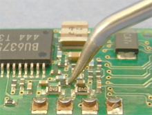
Shape J makes it possible to keep the handpiece at a natural angle.
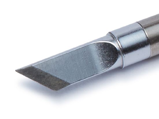
Shape K is similar to a knife blade.
It is good for drag soldering if laying down the knife blade, and it is good for soldering tiny components in the narrow spaces if standing the blade straight.
Show the example of use Close the examples of use
(QFP)Lay the blade down and drag slowly in the direction of the red arrows.
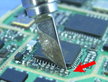
Place the blade edge on the leads of the IC chip.
Soldering tip with concave on the top.
It heats the land and the through-hole component leads effectively by making a bigger contact area with the concave.
It is effective to avoid insufficient PTH fill.
Show the example of use Close the examples of use

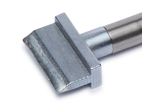
The spatula type heats all the leads of one side of the IC or connectors with significant width at the same time.
Best suited for thermal compression of FPC and soldering on shielded case.
Show the example of use Close the examples of use